
Building an Amiga to TV video cable
Understanding the Amiga video port
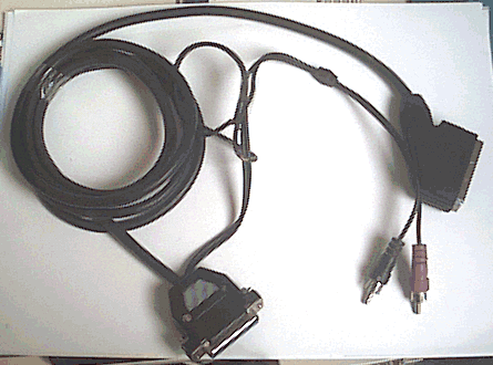
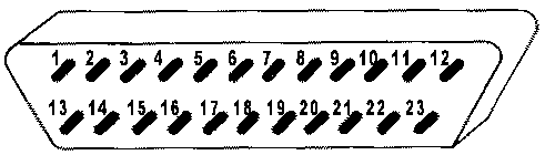
23-pin male RGB video connector.
CAUTION! Pins 21, 22 and 23 of the RGB connector supply power to external equipment.
Connect these pins ONLY IF the peripheral receives its power through them.
The following table lists the function of each pin.
| Pin | Name | Description |
|
1
|
XCLK* | External clock |
|
2
|
XCLKEN* | External clock enable (47 ohms) |
|
3
|
RED | Analogue red (75 ohms) |
|
4
|
GREEN | Analogue green (75 ohms) |
|
5
|
BLUE | Analogue blue (75 ohms) |
|
6
|
DI | Digital intensity (47 ohms) |
|
7
|
DB | Digital blue (47 ohms) |
|
8
|
DG | Digital green (47 ohms) |
|
9
|
DR | Digital red (47 ohms) |
|
10
|
CSYNC* | Composite sync (47 ohms) |
|
11
|
HSYNC* | Horizontal sync (47 ohms) |
|
12
|
VSYNC* | Vertical sync (47 ohms) |
|
13
|
GNDRTN | Return for XCLKEN* |
|
14
|
ZD* | Zero detect (47 ohms) |
|
15
|
Cl* | Clock output (47 ohms) |
|
16
|
GND | Ground |
|
17
|
GND | Ground |
|
18
|
GND | Ground |
|
19
|
GND | Ground |
|
20
|
GND | Ground |
|
21
|
-12 V | -12 volts (50 mA) |
|
22
|
+12 V | + 12 volts (100 mA) |
|
23
|
+5V | +5 volts (100 mA) |
* = active-low signal.
Design:
You will need:
1 connector: 23-pin female.
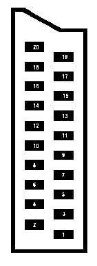
1 SCART plug to connect to the TV.
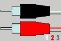
2 RCA plugs for audio.
2 resistors for correct TV display.
1 length of 10-core cable to suit your requirements.
Wiring:
|
|||||||||||||||||||||||||||||||||||||||||||||||||||||||||
 |
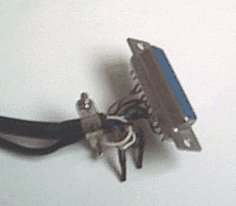 |
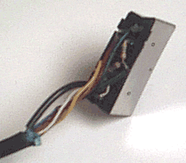
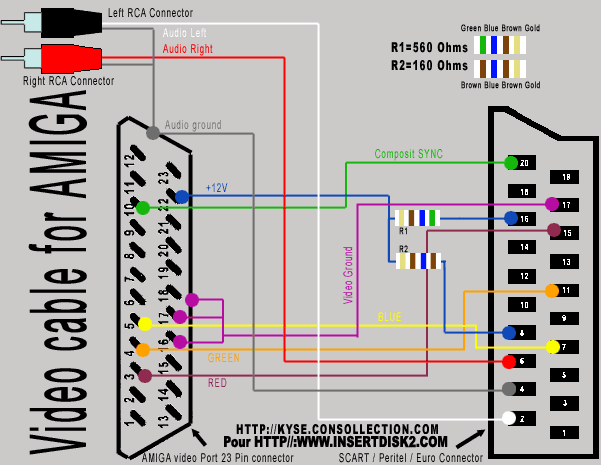
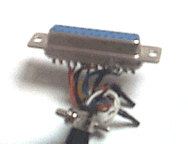
Another wiring guide is available: Amiga to SCART video cable. The two guides provide different information. The KYSE wiring arrangement was prepared using a commercially purchased cable.
Caution: we accept no responsibility for damage to equipment or other loss if problems occur.